802.1X Authentication for Wireless and Wired Connections
802.1X Authentication for Wireless and Wired Connections
Introduction
Description
The project demonstrates Radius authentication for three types of access.
- VTY and Console access to Cisco IOS devices, specifically a 3550 switch
- User authentication for access at wired ports
- User authentication for wireless access
The project integrates the CCNA Wireless class with the CCNA Security class. The project also demonstrates that Cisco wireless could be configured for WPA-2 encryption with 802.1X authentication.
Participants:
- Greg Polanski
- Mark Benolken
802.1X Basics
802.1X authentication has 3 components.
- Supplicant. The supplicant is the device that wants to attach to the WLAN or LAN. The phrase, supplicant, is also used to describe the software in the Windows laptop/desktop that provides authentication credentials.
- Authenticator. Device that controls access to the network. The authenticator queries the supplicant for credentials and passes the credentials to the authentication server for verification. The switch is the authenticator for wired access points. The Wireless LAN Controller (WLC) is the authenticator for wireless access.
- Authentication Server. The authentication server validates the credentials. The authentication server is TekRADIUS LT on a Windows 7 laptop.
The Windows supplicant interacts with the Radius server in two ways, with and without a certificate. The interaction is determined by the “Validate Server Certificate” setting in the “Protected EAP Properties” window.
- Certificate. If the “Validate Server Certificate” setting is checked, the Windows supplicant uses a certificate as part of the credential exchange with the Radius Server. In a corporate environment, this certificate can be pushed to the corporate laptops. In this project, a self signed certificate was created on the radius server and was copied to the laptop.
- No Certificate. If the “Validate Server Certificate” setting is clear, the Windows supplicant does not use the certificate as part of the credential interaction.
Demonstration
The demonstration consisted of the following activities.
- Windows 7 connection to Wireless Data SSID with username and password authentication
- Windows 7 connection to Wired Data VLAN with username and password authentication
- Windows XP connection to Wireless Data SSID with username and password authentication
- Windows XP connection to Wired Data VLAN with username and password authentication
- Ssh connection to 3550 Switch with radius authentication
The Windows configuration for 802.1X authentication required the following activities.
- Enabling authentication in the wireless network definition. Two options were explored.
- Using a certificate between the laptop and the radius server
- Not using a certificate between the laptop and the radius server
- Enabling 802.1X authentication on the wired interface
Configuration
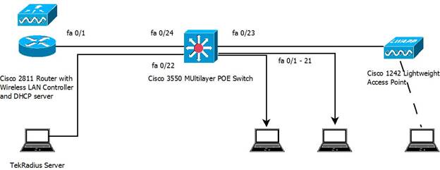
The project used the following equipment.
- Cisco 2811 Router with Wireless LAN Controller module
- Cisco 3550 POE Switch with Layer 2 and Layer 3 capabilities
- Cisco 1242 Wireless Access Point
- Windows 7 and Windows XP laptops
The router hosted the wireless controller and provided DHCP services both to the wired and wireless VLANs. The router used EIGRP and connected to the switch via a layer 3 link (172.16.252.0/30). The 3550 switch provided power to the access point, access control on the wired ports, and relayed DHCP requests to the router.
Windows 7 Laptop
Wireless access has several selections for authentication and encryption Three examples are shown below. One goal of this project was to identify the end user differences when using alternate connection techniques.
- Open. No Encryption, No Authentication
- WPA2-PSK. Encryption, with authentication based upon a fixed password
- WPA2-Enterprise. Encryption with authentication based upon credentials that are unique to the individual.
Open. Most public Wifi hotspots, such as hotspots at coffee shops and public libraries are open. At Inver Hills CC, the SSID, ihcc, is open. The laptop detects the SSID and the owner clicks “Connect”, and the laptop is on the network. The SafeConnect web page is accessible only after the wireless connection is complete. All wireless traffic is not encrypted and can be snooped by others within radio range.
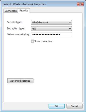
WPA2-PSK. WPA2-PSK is common in the home environment. A pre-shared key is set in the laptop and the wireless access point. The laptop owner must define the wireless network and set the key. An example of the configuration screen follows.
WPA2-Enterprise. The WPA2-Enterprise uses authentication that is unique to the individual. In a corporate environment using Active Directory, the laptop and then the user authenticates to the wireless using AD credentials. The wireless controller checks the credentials via a Radius or TACACS+ server against AD. In a corporate environment, authentication can be seamless since the wireless configuration and authentication certificate can be pushed to the laptop when it is configured and the laptop caches the user’s AD credentials.
In an environment where the end user owns the laptop, the wireless network must be configured.
Wireless Network Configuration
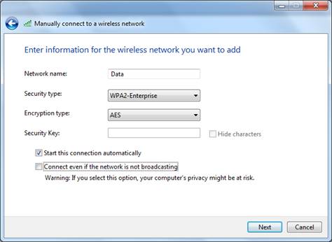
When using encryption and authentication, the wireless network must be defined on the laptop. The following screen shots focus on authentication. The wireless network definition begins with “Set up a new connection or network” or “Manage wireless networks” on the “Network and Sharing Center” screen.
Define the SSID name, the security, the encryption, and whether the connection should be automatic. The SSID is “Data”.
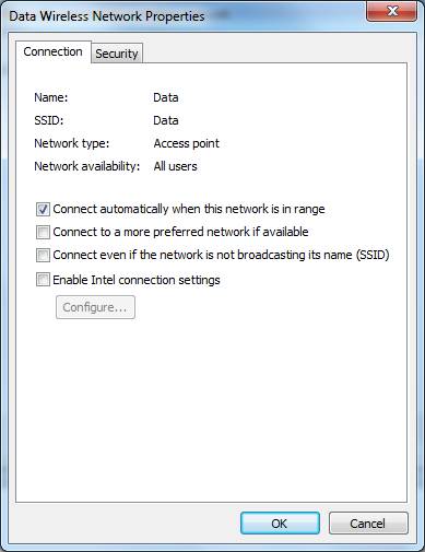
Confirm the settings.
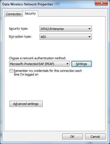
Select the “Security” tab to configure the authentication. Protected EAP (PEAP) is the correct setting. Click on “Settings” to reach the next screen.
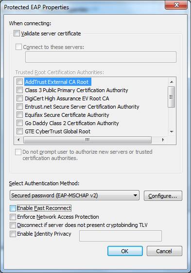
The check box, “Validate server certificate”, affects how the laptop supplicant interacts with the Radius server. If the box is checked, the laptop must have a certificate from the Radius server. The authentication credentials can be read only by the known Radius server. If the laptop authenticates, the radius server is trusted, which means the access point and network are trusted. No one can setup an “evil twin” access point that looks like a production AP and fool the laptop. The cost is that the certificate must be installed on the laptop.
The example shows the configuration where a certificate is not needed, since the checkbox is clear. Clear the Fast Reconnect check box unless you are using cached credentials. Click “Configure …” to go to the next screen.
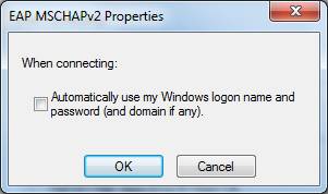
The following popup determines if a authentication popup appears. If the windows login on the laptop uses the same name and password that is needed for wireless authentication, check the box. The credentials will be passed to the access point automatically. In a corporate environment with AD, the box is checked so authentication to the wireless is automatic.
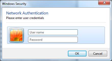
If the checkbox is clear, the following popup will appear so the user can enter the userame and password directly.
References
- http://windows.microsoft.com/en-US/windows-vista/Enable-802-1X-authentication
- http://www.globalknowledge.ae/knowledge%20centre/white%20papers/networking%20%20wireless/wpa2%20security%20choosing%20the%20ri.aspx
Wired Configuration
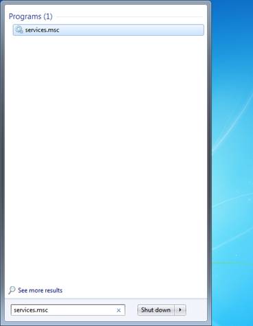
802.1X authentication for a wired connection begins with starting the service on the system. The services screen is reached through the command, “services.msc”. Here the command is typed in the Run window.
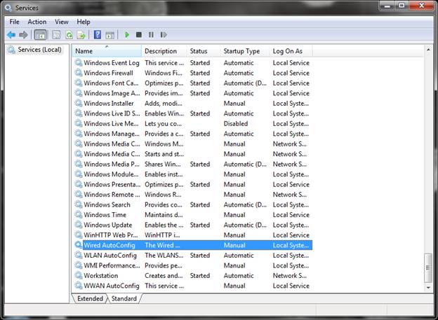
When the Services window appears, select the “Standard” tab (at the bottom). Scroll down and select “Wired AutoConfig”. Right click to “Start” or select “Start” from the “Action” menu.
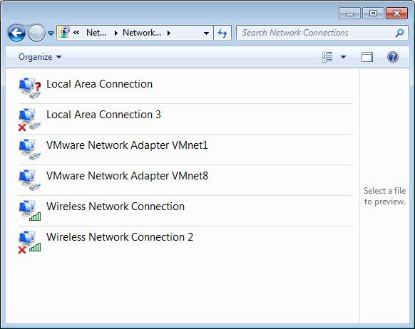
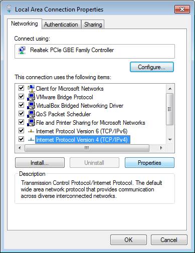
The authentication properties may be edited only after the “Wired Auto Config” service is running. The administration sequence, “Control Panel”, “Network and Internet”, “Network Connections”, leads to the following screen. Select”Local Area Connection”.
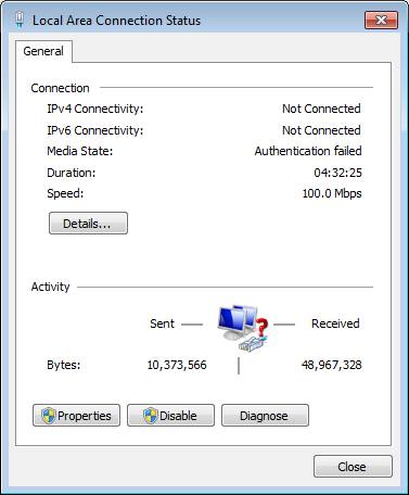
In the “Local Area Connection Status” screen, select “Properties”.
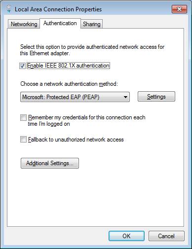
Select the Authentication tab at the top of the “Local Area Connection Properties” window. If the “Wired Auto Config” service is not running, the “Authentication” tab is not visible
Enable the 802.1X authentication.
The “Protected EAP Properties” window is the same as the configuration for the wireless access. The certificate is not needed, since the checkbox is clear. Clear the Fast Reconnect check box unless you are using cached credentials. Click “Configure …” to go to the next screen.
The following popup determines if a authentication popup appears. If the windows login on the laptop uses the same name and password that is needed for wireless authentication, check the box. The credentials will be passed to the access point automatically. In a corporate environment with AD, the box is checked so authentication to the wireless is automatic.
Windows XP Laptop
The wireless and wired configuration steps for a Windows XP laptop is similar to the effort for Windows 7. Windows XP caches the credentials in the registry. The activity to clear the credentials is documented in http://support.microsoft.com/kb/823731
Reference
801.2X With A Certificate
The wireless authentication was also tested with a certificate. The activities included the following.
- Downloading and installing TekCERT from http://www.tekradius.com/release/tekcert.zip.
- Creating a self-signed certificate
- Exporting the certificate in .pfx format. See http://www.yasinkaplan.com/tekcert.asp
- Importing the certificate on the laptop
The configuration setting on the laptop was checking “Validate server certificate” in the “Protected EAP Properties” window.
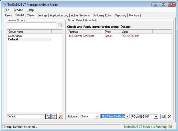
The User or the Group must be configured to use the certificate in the TekRADIUS server. The certificate is part of the group setting, below. Alternatively, the setting could be a user configuration. The screen image is in the TekRADIUS configuration section.
TekRADIUS References
- http://tekradius.com/
- http://tekradius.com/support.html
- http://tekradius.com/Docs/Manual.pdf
- http://www.yasinkaplan.com/tekcert.asp
Cisco Switch Configuration
The configuration statements for the 3550 switch follow. The authentication sections for VTY and console access are identical in the switch and the router.
Authentication
Authentication for the data ports, vty access, and the console port is enabled through the commands, below. AAA is enabled. Console and vty login is authenticated through radius. When the radius server is not accessible, local user authentication is used. The radius server uses ports 1812 and 1813 for authentication and accounting. The dot1x command enables dot1x access control on the data ports.
aaa new-model

aaa authentication login default group radius local
aaa authentication dot1x default group radius

radius-server host 172.16.106.11 auth-port 1812 acct-port 1813 key WinRadius

dot1x system-auth-control
Data Ports
The configuration for the data ports is below. The global configuration command enables BPDUguard on all portfast ports. If a switch is connected to any port, the port will change to an error disabled stated. This also prevents loops if a user connects two switch ports together.
The switchport commands set the port to access mode and define the data and voice vlans. Three dot1x commands are shown. When the configuration command, “dot1x port-control auto”, was added, the IOS automatically added the other commands. The phrase, “dot1x pae authenticator”, assures authentication in legacy configurations. The “dot1x violation-mode protect” command means that connecting systems that fail authentication will be quietly blocked. The word, protect, means that no log messages nor SNMP traps will be generated. One option that is not shown is a “guest” vlan. The interface configuration statement, “dot1x guest-vlan 20”, would assign the device to vlan 20. This vlan is assumed to have limited access.
In production, Quality of Service should be added to the configuration to support IP Phones. QoS is not shown since the project focus was 802.1X authentication.
spanning-tree portfast bpduguard default

interface FastEthernet0/1
 description End user data ports
 switchport access vlan 110
 switchport voice vlan 111
 switchport mode access

 dot1x pae authenticator
 dot1x port-control auto
 dot1x violation-mode protect

 spanning-tree portfast

!
References
- http://www.cisco.com/en/US/docs/switches/lan/catalyst3550/software/release/12.1_13_ea1/configuration/guide/Sw8021x.html#wp1049580
- http://www.cisco.com/en/US/docs/switches/lan/catalyst3550/software/release/12.2_25_see/configuration/guide/swstpopt.html
- http://www.cisco.com/en/US/docs/ios/12_4t/12_4t11/ht_8021x.html
- http://www.cisco.com/en/US/prod/collateral/iosswrel/ps6537/ps6586/ps6660/ps6807/prod_white_paper0900aecd805a5ab5.html
Wireless Access Point Port
The switch port that is assigned to the wireless access point is does not require 802.1X authentication. The “force-authorized” phrase means that the port is enabled.
interface FastEthernet0/23
 description Wireless Access Point
 switchport access vlan 110
 switchport mode access
 spanning-tree portfast

 dot1x port-control force-authorized
The port can be constrained to support ONLY the wireless access point through the following statements. The default mode is to shut down the port if a violation occurs.
switchport port-security maximum 1
switchport port-security mac-address sticky
Radius Server Port
The switch port that is assigned to the radius server does not require 802.1X authentication. The “force-authorized” phrase means that the port is enabled. Switchport port-security statements could be used to permit only the radius server at this port.
interface FastEthernet0/22
 description Radius Server
 switchport access vlan 110
 switchport mode access
 spanning-tree portfast

 dot1x port-control force-authorized
Logging
Logging on the switch and router was configured as follows. The “localtime” phrase configures the logging service and console to display a clock and calendar based time rather than the delta time since the device boot. The devices are set to US/Central timezone.
service timestamps debug datetime msec localtime
service timestamps log datetime msec localtime

logging trap 6
logging 172.16.106.11
Routing
The 3550 switch was configured with a layer 3 connection to the router. The command, “no switchport”, set port 24 to communicate on layer 3. All data ports were configured as EIGRP passive ports to suppress EIGRP routing traffic on the ports.
ip routing

interface FastEthernet0/24
 description Connect to 2811 Router port fa 0/1
 no switchport
 ip address 172.16.252.2 255.255.255.252


router eigrp 10
 passive-interface default
 no passive-interface FastEthernet0/24
 network 172.16.0.0
 network 172.17.0.0
!
ip classless
VTY Access
Vty and console access uses radius authentication since the “… login default …” configuration is defined. Local authentication, which checks user names that are defined on the switch or router, is used only if the radius server does not respond. The transport command mandates that only ssh is used for remote access.
aaa authentication login default group radius local

line con 0
 session-timeout 30
 exec-timeout 20 0
 logging synchronous

line vty 0 4
 session-timeout 30
 logging synchronous
 transport input ssh
Cisco Router Configuration
Router – Switch Link
The router and switch were connected at Layer 3. Router interface FastEtherenet 0/1 was connected to switch port FastEthernet 0/24. Both devices used EIGRP.
interface FastEthernet0/1
 description Connect to 3560 POE Switch (usually port fa 0/24)
 ip address 172.16.252.1 255.255.255.252
 duplex auto
 speed auto
!

router eigrp 10
 network 172.16.0.0
 network 172.17.0.0
 no auto-summary
!
DHCP
The router, switch, and wireless controller used the following VLANs and addresses.
| VLAN | Network | Description |
|---|---|---|
| 100 | 172.16.100.0/24 | WLC Access Point Management |
| 110 | 172.16.106.0/24 | Wired Data |
| 111 | 172.17.106.0/24 | Wired Voice |
| 112 | 172.16.116.0/24 | Wireless Data |
| 113 | 172.17.116.0/24 | Wireless Voice |
| 114 | 172.16.126.0/24 | Wireless Guest |
| 172.16.252.0/30 | Router/Switch L3 network | |
| 172.16.1.1/24 | WLC Interface | |
| 172.16.106.11 | Radius Server |
Syslog Server
The router was configured as the DHCP server for both the wired and wireless VLANs. One benefit is that all DHCP definitions are one location. The configuration also emulates a production environment that uses a centralized DHCP server.
The “excluded-address” statements identify addresses that are not part of DHCP and may be statically assigned. One example is the switch’s management address, 172.16.106.5. The “AP Management” pool is not really used, but it sets aside addresses for use in the WLAN controller.
Option 43 is used by the wireless access point to find the controller. The first 16 bits, f104, is a fixed value the must be part of the definition. The last 32 bits, ac10.6464, is the hexadecimal representation of the address, 172.16.100.100. This is the address in the wireless controller that responds to the access points. Option 60 limits option 43 to DHCP clients that are the Cisco 1242 access points. Option 150 in the Voice VLAN is the address of the TFTP server for CME or CUCM.
The last DHCP pool shows how to assign a specific address to a device. The DHCP pool is just one address, which is specified by the “host” statement. The client identifier phrase specifies the MAC address where with theprepended byte, 0x01. This is the same format as displayed for the command, “show ip dhcp binding”. 172.16.106.11 is the laptop that is running the Radius server.
ip dhcp excluded-address 172.16.106.1 172.16.106.10
ip dhcp excluded-address 172.17.106.1 172.17.106.10
ip dhcp excluded-address 172.17.116.1 172.17.116.10
ip dhcp excluded-address 172.16.116.1 172.16.116.10
ip dhcp excluded-address 172.16.126.1 172.16.126.10
!
ip dhcp pool Data-Devices
   network 172.16.106.0 255.255.255.0
   default-router 172.16.106.1
   option 43 hex f104.ac10.6464
   option 60 ascii "Cisco AP c1242"
!
ip dhcp pool Voice-Devices
   network 172.17.106.0 255.255.255.0
   default-router 172.17.106.1
   option 150 ip 172.17.106.1
!
ip dhcp pool Wireless-Data
   network 172.16.116.0 255.255.255.0
   default-router 172.16.116.1
   lease 0 6
!
ip dhcp pool Wireless-Voice
   network 172.17.116.0 255.255.255.0
   default-router 172.17.116.1
   lease 0 6
   option 150 ip 172.17.106.1
!
ip dhcp pool Wireless-Guest
   network 172.16.126.0 255.255.255.0
   default-router 172.16.126.1
   lease 0 2
!
ip dhcp pool AP-Management
   network 172.16.100.0 255.255.255.0
   default-router 172.16.100.1
!
ip dhcp pool GMPlaptop
   host 172.16.106.11 255.255.255.0
   client-identifier 0198.4be1.96f9.81
   client-name gmplaptop
!
Time
The router is set as the NTP master. The following commands set the time zone and the NTP server.
clock timezone CST -6
clock summer-time CDT recurring
ntp server 172.16.252.1
TekRADIUS Server
TekRADIUS LT is the radius server. It was installed on Windows 7. The web site is http://www.tekradius.com.
TekRADIUS User Management
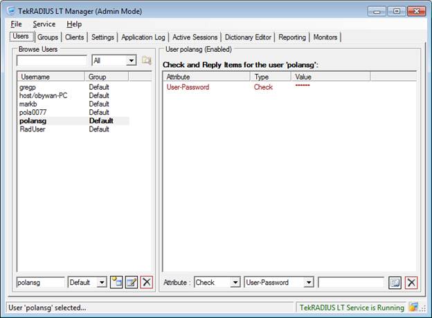
The following screen shows the user management interface. The only user attribute that is defined is the password.
Users may be associated with different groups to manage attributes and privileges. The default group usually has no attributes. Here the TLS certificate attribute is defined as part of using a certificate during Windows authentication.
Radius Clients
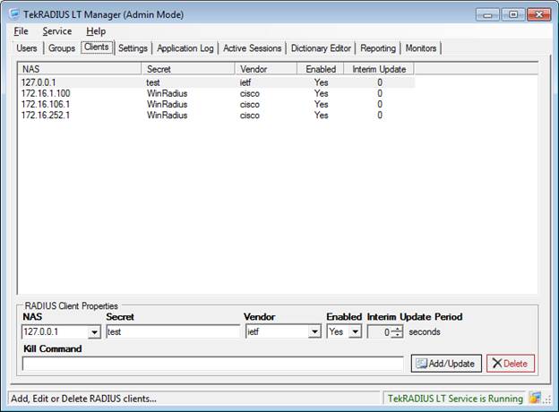
The Client screen lists the 3 clients, which are the Wireless LAN Controller, the switch, and the router. Here, the radius clients are explicitly listed. The software has an option where any client that uses the pre-shared secret may connect to the radius server.
Radius Server Parameters
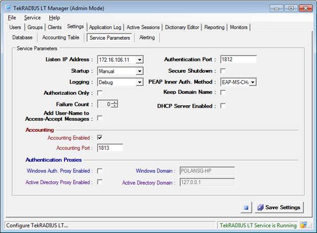
The radius server configuration follows. The most important parameters on this screen are the listening address, the automatic or manual start option, the logging level, and the authentication and accounting ports.
Cisco Wireless LAN Controller
Several entities are used when configuring a Wireless LAN Controller.
- Controller address. An address must be assigned to the controller interface to allow CLI access and to serve as the default route for inter faces within the controller. The address is defined as follows.
interface wlan-controller1/0
 ip address 172.16.1.1 255.255.255.0
!
- WLAN. A WLAN is defined for each SSID that is used by the access points. For convenience, the WLAN name is the same as the SSID. The WLAN is associated with a VLAN through the interface assignment.
- Interfaces. The interfaces connect the WLAN to and address and VLAN. An interface has a name, an IP address, and a VLAN number. For convenience, the interface name is the same as the associated WLAN name.
- Management Addresses. The WLAN controller has two management addresses. The management address is the web server address. The second address is the “AP Management” address. The AP Management address is used by the access points and is the value used in DHCP option 43.
In the router, the Wireless LAN Controller interface is configured as follows.
interface wlan-controller1/0
 ip address 172.16.1.1 255.255.255.0
!
interface wlan-controller1/0.100
 encapsulation dot1Q 100
 ip address 172.16.100.1 255.255.255.0
!
interface wlan-controller1/0.112
 description Wireless Data
 encapsulation dot1Q 112
 ip address 172.16.116.1 255.255.255.0
!
interface wlan-controller1/0.113
 description Wireless Voice
 encapsulation dot1Q 113
 ip address 172.17.116.1 255.255.255.0
!
interface wlan-controller1/0.114
 description Wireless-Guest
 encapsulation dot1Q 114
 ip address 172.16.126.1 255.255.255.0
!
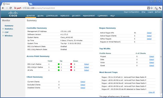
WLC Summary Screen
The system status is visible on the Summary screen. The information includes the number of access points and the number
WLAN Screen
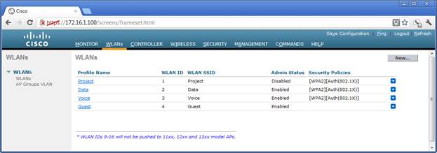
The wireless LANs are defined in the WLAN screen. The SSIDs are listed in the third column. Three are being broadcast.
WLAN Configuration and Encryption
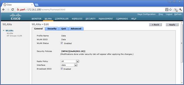
One WLAN configuration screen follows. The “Enabled” state shows that the WLAN is active in the access points. The security policy is displayed here, but is defined in the “Security” tab. The WLAN is connected to an IP address via the interface selection. The SSID is being broadcast.
WLAN Encryption
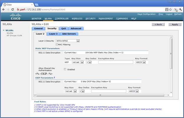
The WPA2 encryption is defined.
WLAN Authentication
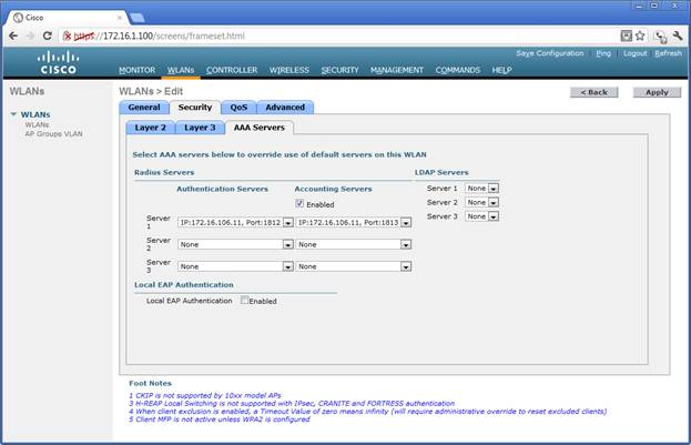
Authentication is enabled for this WLAN and the radius server is specified for authorization and accounting. Multiple servers may be defined.
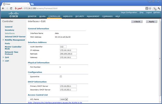
Interfaces
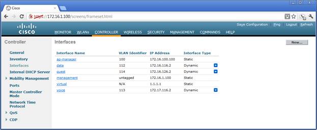
The controller interfaces are defined in this screen. Notice that the addresses are in the same network as the corresponding subinterface in the WLAN controller interface definition.
Interface Details
The interface address is in the same subnet as the address that is defined in the router’s wlan controller subinterface.
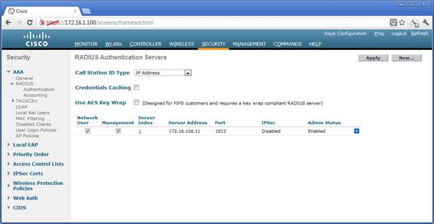
Radius Server Definition
The radius servers, port numbers, and shared secret are defined in this screen. The server information is used in the WLAN authentication screen.
Appendix
Router Configuration
Current configuration : 4154 bytes
!
! Last configuration change at 16:46:52 CDT Mon Apr 9 2012
! NVRAM config last updated at 16:46:57 CDT Mon Apr 9 2012
!
version 12.4
service timestamps debug datetime msec localtime
service timestamps log datetime msec localtime
service password-encryption
!
hostname TELRTR1
!
boot-start-marker
boot-end-marker
!
logging message-counter syslog
enable secret 5 $1$yrf.$aceRCoh602PSjdRhAAXtb.
!
aaa new-model
!
!
aaa authentication login default group radius enable
aaa authentication dot1x default group radius
!
!
aaa session-id common
memory-size iomem 10
clock timezone CST -6
clock summer-time CDT recurring
!
dot11 syslog
ip source-route
!
!
ip cef
ip dhcp excluded-address 172.16.106.1 172.16.106.10
ip dhcp excluded-address 172.17.106.1 172.17.106.10
ip dhcp excluded-address 172.17.116.1 172.17.116.10
ip dhcp excluded-address 172.16.116.1 172.16.116.10
ip dhcp excluded-address 172.16.126.1 172.16.126.10
!
ip dhcp pool Data-Devices
   network 172.16.106.0 255.255.255.0
   default-router 172.16.106.1
   option 43 hex f104.ac10.6464
   option 60 ascii "Cisco AP c1242"
!
ip dhcp pool Wireless-Data
   network 172.16.116.0 255.255.255.0
   default-router 172.16.116.1
   lease 0 6
!
ip dhcp pool Wireless-Voice
   network 172.17.116.0 255.255.255.0
   default-router 172.17.116.1
   lease 0 6
!
ip dhcp pool Wireless-Guest
   network 172.16.126.0 255.255.255.0
   default-router 172.16.126.1
   lease 0 2
!
ip dhcp pool AP-Management
   network 172.16.100.0 255.255.255.0
   default-router 172.16.100.1
!
ip dhcp pool GMPlaptop
   host 172.16.106.11 255.255.255.0
   client-identifier 0198.4be1.96f9.81
   client-name gmplaptop
!
!
ip dhcp class Lab-Data
!
no ip domain lookup
ip domain name ihcc.net
no ipv6 cef
!
multilink bundle-name authenticated
!
!
!
!
!
!
!
!
!
!
!
!
!
!
!
!
!
!
!
!
!
!
!
voice-card 0
!
!
!
!
!
vtp domain CISCO
vtp mode transparent
username polansg privilege 15 secret 5 $1$eDuT$FcqhQqGjhWcs69LmIUNZA/
username admin privilege 15 secret 5 $1$dsOK$PxnQvqldLIwJVKcN0SyBY0
archive
 log config
  hidekeys
!
!
!
!
!
!
!
!
!
interface Loopback0
 ip address 172.16.251.1 255.255.255.255
!
interface FastEthernet0/0
 description idle
 no ip address
 shutdown
 duplex auto
 speed auto
!
interface Service-Engine0/0
 no ip address
 shutdown
!
interface FastEthernet0/1
 description Connect to 3560 POE Switch (usually port fa 0/24)
 ip address 172.16.252.1 255.255.255.252
 duplex auto
 speed auto
!
interface Serial0/0/0
 no ip address
 shutdown
 no fair-queue
 clock rate 2000000
!
interface Serial0/0/1
 no ip address
 shutdown
 clock rate 2000000
!
interface wlan-controller1/0
 ip address 172.16.1.1 255.255.255.0
!
interface wlan-controller1/0.100
 encapsulation dot1Q 100
 ip address 172.16.100.1 255.255.255.0
!
interface wlan-controller1/0.112
 description Wireless Data
 encapsulation dot1Q 112
 ip address 172.16.116.1 255.255.255.0
!
interface wlan-controller1/0.113
 description Wireless Voice
 encapsulation dot1Q 113
 ip address 172.17.116.1 255.255.255.0
!
interface wlan-controller1/0.114
 description Wireless-Guest
 encapsulation dot1Q 114
 ip address 172.16.126.1 255.255.255.0
!
router eigrp 10
 network 172.16.0.0
 network 172.17.0.0
 no auto-summary
!
ip forward-protocol nd
ip http server
ip http authentication local
no ip http secure-server
!
!
!
logging 172.16.106.11
!
!
!
!
!
radius-server host 172.16.106.11 auth-port 1812 acct-port 1813 key 7 0631062F7E4F0D101004
!
control-plane
!
!
!
voice-port 0/1/0
!
voice-port 0/1/1
!
voice-port 0/2/0
!
voice-port 0/2/1
!
!
!
!
!
!
!
banner motd ^C Unauthorized Access is Prohibited ^C
!
line con 0
 exec-timeout 0 0
 buffer-length 300
 logging synchronous
 history size 100
line aux 0
line 66
 no activation-character
 no exec
 transport preferred none
 transport input all
 transport output pad telnet rlogin lapb-ta mop udptn v120 ssh
line 194
 no activation-character
 no exec
 transport preferred none
 transport input all
 transport output pad telnet rlogin lapb-ta mop udptn v120 ssh
line vty 0 4
 session-timeout 10
 buffer-length 300
 logging synchronous
 history size 100
 transport input ssh
!
scheduler allocate 20000 1000
ntp master
end
Switch Configuration
Current configuration : 9285 bytes
!
! Last configuration change at 16:19:17 CDT Mon Apr 9 2012 by polansg
! NVRAM config last updated at 16:20:19 CDT Mon Apr 9 2012 by polansg
!
version 12.2
no service pad
service timestamps debug datetime msec localtime
service timestamps log datetime msec localtime
service password-encryption
!
hostname TELSW1-DLS1
!
enable secret 5 $1$21lk$o8aw9KQPOHquvd/KeHScK0
!
username polansg privilege 15 secret 5 $1$eDuT$FcqhQqGjhWcs69LmIUNZA/
username admin privilege 15 secret 5 $1$dsOK$PxnQvqldLIwJVKcN0SyBY0
aaa new-model
!
!
aaa authentication login default group radius enable
aaa authentication dot1x default group radius
!
!
!
aaa session-id common
clock timezone CST -6
clock summer-time CDT recurring
ip subnet-zero
ip routing
no ip domain-lookup
ip domain-name ihcc.net
!
!
!
crypto pki trustpoint TP-self-signed-1832549888
 enrollment selfsigned
 subject-name cn=IOS-Self-Signed-Certificate-1832549888
 revocation-check none
 rsakeypair TP-self-signed-1832549888
!
!
crypto pki certificate chain TP-self-signed-1832549888
 certificate self-signed 01
  30820244 308201AD A0030201 02020101 300D0609 2A864886 F70D0101 04050030
  31312F30 2D060355 04031326 494F532D 53656C66 2D536967 6E65642D 43657274
  69666963 6174652D 31383332 35343938 3838301E 170D3933 30333031 30303133
  35375A17 0D323030 31303130 30303030 305A3031 312F302D 06035504 03132649
  4F532D53 656C662D 5369676E 65642D43 65727469 66696361 74652D31 38333235
  34393838 3830819F 300D0609 2A864886 F70D0101 01050003 818D0030 81890281
  8100C747 06F874A3 05026E04 8225F0C6 EF9BA342 A7907FA1 948F529B 0A8D575F
  CCEB789F 64BC389D 710B9048 EDF2721B 2C046A38 DA70CA5F D6933F96 2C46276D
  C1AF7A6D 2B63AE47 92E7FEFF 281A3A8C 2B50A4D3 4644225D 644E0FB1 4E51FEB4
  5675A44F E4CE97FB BD9BD510 CAC0FD48 4E2B5BD6 418A99C2 FBC27227 41539E24
  AF6F0203 010001A3 6C306A30 0F060355 1D130101 FF040530 030101FF 30170603
  551D1104 10300E82 0C54454C 5357312D 444C5331 2E301F06 03551D23 04183016
  80145DF8 A5D8593B 475F05D2 96BC0A08 DAFC9DA2 4E11301D 0603551D 0E041604
  145DF8A5 D8593B47 5F05D296 BC0A08DA FC9DA24E 11300D06 092A8648 86F70D01
  01040500 03818100 8F961DDE 3CBCB0CD 6013B910 0B7C0200 D5F0BC46 DF513CED
  B9E3B1DA 80B27BD2 09169663 D2FF2E8C 0F9E02DD 4A52A0E9 9BED78EE CDE1ACCD
  3826DF7F E559F3BD B6DE2C3D 8D83BB5F 3FD0C142 4F98253C 9040A5E3 377C9A72
  FA5D23D0 E32AD9A0 16FAD25A 296C4771 7881884A 38DD0333 FE7B2516 5716CD2F
  B363FFB4 41D6A356
  quit
dot1x system-auth-control
!
!
spanning-tree mode pvst
spanning-tree portfast bpduguard default
spanning-tree extend system-id
!
vlan internal allocation policy ascending
!
ip ssh version 2
!
!
!
!
!
interface FastEthernet0/1
 description End user data ports
 switchport access vlan 110
 switchport mode access
 switchport voice vlan 111
 dot1x pae authenticator
 dot1x port-control auto
 dot1x violation-mode protect
 spanning-tree portfast
!
interface FastEthernet0/2
 description End user data ports
 switchport access vlan 110
 switchport mode access
 switchport voice vlan 111
 dot1x pae authenticator
 dot1x port-control auto
 dot1x violation-mode protect
 spanning-tree portfast
!
interface FastEthernet0/3
 description End user data ports
 switchport access vlan 110
 switchport mode access
 switchport voice vlan 111
 dot1x pae authenticator
 dot1x port-control auto
 dot1x violation-mode protect
 spanning-tree portfast
!
interface FastEthernet0/4
 description End user data ports
 switchport access vlan 110
 switchport mode access
 switchport voice vlan 111
 dot1x pae authenticator
 dot1x port-control auto
 dot1x violation-mode protect
 spanning-tree portfast
!
interface FastEthernet0/5
 description End user data ports
 switchport access vlan 110
 switchport mode access
 switchport voice vlan 111
 dot1x pae authenticator
 dot1x port-control auto
 dot1x violation-mode protect
 spanning-tree portfast
!
interface FastEthernet0/6
 description End user data ports
 switchport access vlan 110
 switchport mode access
 switchport voice vlan 111
 dot1x pae authenticator
 dot1x port-control auto
 dot1x violation-mode protect
 spanning-tree portfast
!
interface FastEthernet0/7
 description End user data ports
 switchport access vlan 110
 switchport mode access
 switchport voice vlan 111
 dot1x pae authenticator
 dot1x port-control auto
 dot1x violation-mode protect
 spanning-tree portfast
!
interface FastEthernet0/8
 description End user data ports
 switchport access vlan 110
 switchport mode access
 switchport voice vlan 111
 dot1x pae authenticator
 dot1x port-control auto
 dot1x violation-mode protect
 spanning-tree portfast
!
interface FastEthernet0/9
 description End user data ports
 switchport access vlan 110
 switchport mode access
 switchport voice vlan 111
 dot1x pae authenticator
 dot1x port-control auto
 dot1x violation-mode protect
 spanning-tree portfast
!
interface FastEthernet0/10
 description End user data ports
 switchport access vlan 110
 switchport mode access
 switchport voice vlan 111
 dot1x pae authenticator
 dot1x port-control auto
 dot1x violation-mode protect
 spanning-tree portfast
!
interface FastEthernet0/11
 description End user data ports
 switchport access vlan 110
 switchport mode access
 switchport voice vlan 111
 dot1x pae authenticator
 dot1x port-control auto
 dot1x violation-mode protect
 spanning-tree portfast
!
interface FastEthernet0/12
 description End user data ports
 switchport access vlan 110
 switchport mode access
 switchport voice vlan 111
 dot1x pae authenticator
 dot1x port-control auto
 dot1x violation-mode protect
 spanning-tree portfast
!
interface FastEthernet0/13
 description End user data ports
 switchport access vlan 110
 switchport mode access
 switchport voice vlan 111
 dot1x pae authenticator
 dot1x port-control auto
 dot1x violation-mode protect
 spanning-tree portfast
!
interface FastEthernet0/14
 description End user data ports
 switchport access vlan 110
 switchport mode access
 switchport voice vlan 111
 dot1x pae authenticator
 dot1x port-control auto
 dot1x violation-mode protect
 spanning-tree portfast
!
interface FastEthernet0/15
 description End user data ports
 switchport access vlan 110
 switchport mode access
 switchport voice vlan 111
 dot1x pae authenticator
 dot1x port-control auto
 dot1x violation-mode protect
 spanning-tree portfast
!
interface FastEthernet0/16
 description End user data ports
 switchport access vlan 110
 switchport mode access
 switchport voice vlan 111
 dot1x pae authenticator
 dot1x port-control auto
 dot1x violation-mode protect
 spanning-tree portfast
!
interface FastEthernet0/17
 description End user data ports
 switchport access vlan 110
 switchport mode access
 switchport voice vlan 111
 dot1x pae authenticator
 dot1x port-control auto
 dot1x violation-mode protect
 spanning-tree portfast
!
interface FastEthernet0/18
 description End user data ports
 switchport access vlan 110
 switchport mode access
 switchport voice vlan 111
 dot1x pae authenticator
 dot1x port-control auto
 dot1x violation-mode protect
 spanning-tree portfast
!
interface FastEthernet0/19
 description End user data ports
 switchport access vlan 110
 switchport mode access
 switchport voice vlan 111
 dot1x pae authenticator
 dot1x port-control auto
 dot1x violation-mode protect
 spanning-tree portfast
!
interface FastEthernet0/20
 description End user data ports
 switchport access vlan 110
 switchport mode access
 switchport voice vlan 111
 dot1x pae authenticator
 dot1x port-control auto
 dot1x violation-mode protect
 spanning-tree portfast
!
interface FastEthernet0/21
 description End user data ports
 switchport access vlan 110
 switchport mode access
 switchport voice vlan 111
 dot1x pae authenticator
 dot1x port-control auto
 dot1x violation-mode protect
 spanning-tree portfast
!
interface FastEthernet0/22
 description Radius Server
 switchport access vlan 110
 switchport mode access
 dot1x pae authenticator
 dot1x violation-mode protect
 spanning-tree portfast
!
interface FastEthernet0/23
 description Wireless Access Point
 switchport access vlan 110
 switchport mode access
 dot1x pae authenticator
 dot1x violation-mode protect
 spanning-tree portfast
!
interface FastEthernet0/24
 description Connect to 2811 Router port fa 0/1 on Router
 no switchport
 ip address 172.16.252.2 255.255.255.252
!
interface GigabitEthernet0/1
 switchport mode dynamic desirable
!
interface GigabitEthernet0/2
 switchport mode dynamic desirable
!
interface Vlan1
 no ip address
 shutdown
!
interface Vlan110
 description Wired Data
 ip address 172.16.106.1 255.255.255.0
 ip helper-address 172.16.251.1
!
!
router eigrp 10
 passive-interface default
 no passive-interface FastEthernet0/24
 network 172.16.0.0
 network 172.17.0.0
!
ip classless
ip http server
ip http authentication local
no ip http secure-server
!
!
logging 172.16.106.11
radius-server host 172.16.106.11 auth-port 1812 acct-port 1813 key 7 0631062F7E4F0D101004
!
control-plane
!
banner motd ^C Unauthorized Access is Prohibited ^C
!
line con 0
 session-timeout 30
 exec-timeout 20 0
 logging synchronous
line vty 0 4
 session-timeout 30
 logging synchronous
 transport input ssh
line vty 5 15
 session-timeout 30
 logging synchronous
 transport input ssh
!
ntp clock-period 17180066
ntp server 172.16.252.1
end
Wireless LAN Controller Configuration
(Cisco Controller) >show running-config
 802.11a cac voice tspec-inactivity-timeout ignore
 802.11a cac voice stream-size 84000 max-streams 2
 802.11b cac voice tspec-inactivity-timeout ignore
 802.11b cac voice stream-size 84000 max-streams 2
  advanced location expiry tags 1200

 advanced location expiry client 150
 advanced location expiry calibrating-client 30
 advanced location expiry rogue-aps 1200

 cdp disable

interface create data 112
interface create guest 114
interface create voice 113

interface address ap-manager 172.16.100.100 255.255.255.0 172.16.100.1
interface address dynamic-interface data 172.16.116.2 255.255.255.0 172.16.116.1
interface address dynamic-interface guest 172.16.126.2 255.255.255.0 172.16.126.1
interface address management 172.16.1.100 255.255.255.0 172.16.1.1
interface address virtual 1.1.1.1
interface address dynamic-interface voice 172.17.116.2 255.255.255.0 172.17.116.1

interface dhcp ap-manager primary 172.16.100.1
interface dhcp dynamic-interface data primary 172.16.252.1 secondary 172.16.252.1
interface dhcp dynamic-interface guest primary 172.16.252.1
interface dhcp management primary 172.16.1.1
interface dhcp dynamic-interface voice primary 172.16.252.1

interface vlan ap-manager 100
interface vlan data 112
interface vlan guest 114
interface vlan voice 113

interface port ap-manager 1
interface port data 1
interface port guest 1
interface port management 1
interface port voice 1

 logging buffered 2
 mesh security eap
 mgmtuser add admin **** read-write
 mobility group domain mg1
 msglog level critical
 network rf-network-name mg1

 radius acct add 1 172.16.106.11 1813 ascii ****
 radius auth add 1 172.16.106.11 1812 ascii ****
 radius auth rfc3576 enable 1

 snmp version v2c enable
 snmp version v3 enable

 syslog 172.16.101.11
 sysname Cisco_e9:b2:60

 time ntp interval 36000
 time ntp server 1 172.16.252.1

 wlan create 1 Project Project
 wlan create 2 Data Data
 wlan create 3 Voice Voice
 wlan create 4 Guest Guest
 wlan interface 2 data
 wlan interface 3 voice
 wlan interface 4 guest
 wlan broadcast-ssid disable 1

 wlan radius_server auth add wlan-id:2 global server index:1
 wlan radius_server acct add wlan-id:2 global server index:1
 wlan radius_server auth add wlan-id:3 global server index:1

 wlan security static-wep-key encryption 2 104 ascii **** 1
 wlan security static-wep-key encryption 3 104 ascii **** 1
 wlan security static-wep-key encryption 4 104 ascii **** 1
 wlan security wpa disable 4
 wlan security wpa wpa1 ciphers tkip enable 1
 wlan security wpa wpa1 ciphers tkip enable 2
 wlan security wpa wpa1 ciphers tkip enable 3
 wlan enable 2

(Cisco Controller) >?
