Link Aggregation Lab: Difference between revisions
(Link Aggregration Project) |
No edit summary |
||
| Line 143: | Line 143: | ||
As a result of our configuration, testing methodology, and testing results we can confirm that link aggregation is an appropriate communications protocol to use when attempting to create redundant linked backbone switches. While it is true that we could negate the performance loss between the added links by using one high speed gigabit connection, we cannot duplicate the reliability of the communication between these switches by using a sole gigabit connection. We therefore can suggest and even recommend that when mission critical systems are used for internetworking, that link aggregation be setup and configured for at least the reliability aspect. | As a result of our configuration, testing methodology, and testing results we can confirm that link aggregation is an appropriate communications protocol to use when attempting to create redundant linked backbone switches. While it is true that we could negate the performance loss between the added links by using one high speed gigabit connection, we cannot duplicate the reliability of the communication between these switches by using a sole gigabit connection. We therefore can suggest and even recommend that when mission critical systems are used for internetworking, that link aggregation be setup and configured for at least the reliability aspect. | ||
<br><br> | |||
Created: 11/19/2011 by Monique Moison and Joshua Platz | |||
Latest revision as of 20:04, 19 November 2011
Objective:
Analyze the performance and reliability of Etherchannel using the IEEE standard Link Aggregation Protocol (LACP) (802.3ad). Equipment:
- (2) Cisco Catalyst 3560 Switch
- (1) 2600 Cisco Router
- (16) Desktop Computers
- (18) Patch Cables (16 for PC’s, 1 for Router->Internet, 1 for Switch->Router)
- (9) Crossover cables (8 for Link Aggregation, 1 for VLAN1 communications)
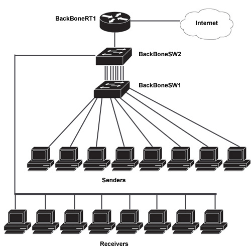
Topology Design
Step 1 – Network Configuration
Begin by establishing connections between the devices to ensure that layer 3 devices can communicate properly infrastructure. This includes setting up two VLANs (1 and 10) that communicate to each other through the connected router. We will also establish internet connectivity to both VLANs for larger scope implementation and functionality.
Configuring internet connectivity:
    BackBoneRT1# configure terminal
    BackBoneRT1(config)# interface FastEthernet 0/0
    BackBoneRT1(config-if)# ip address dhcp
    BackBoneRT1(config-if)# no shutdown
    BackBoneRT1(config-if)# exit
    BackBoneRT1(config)# ip default-gateway 192.168.0.1
Configure NAT:
    BackBoneRT1(config)#ip access-list standard 1
    BackBoneRT1(config-std-nacl)# permit 10.1.0.0 0.0.255.255
    BackBoneRT1(config-std-nacl)# permit 10.10.0.0 0.0.255.255
    BackBoneRT1(config-std-nacl)#exit
    BackBoneRT1(config)# ip nat inside source list 1 interface FastEthernet0/1 overload BackBoneRT1(config)#interface FasstEthernet 0/1
    BackBoneRT1(config-if)# ip nat outside
Configure INTER-VLAN routing:
    BackBoneRT1(config)# interface FastEthernet 0/0
    BackBoneRT1(config-if)# no shutdown
    BackBoneRT1(config-if)# interface FastEthernet 0/0.1
    BackBoneRT1(config-if)#encapsulation dot1q 1
    BackBoneRT1(config-if)#ip address 10.1.0.1 255.255.0.0
    BackBoneRT1(config-if)# interface FastEthernet 0/0.10
    BackBoneRT1(config-if)#encapsulation dot1q 10
    BackBoneRT1(config-if)#ip address 10.10.0.1 255.255.0.0
Default Gateway and Create VLAN10:
    BackBoneSW1# configure terminal
    BackBoneSW1(config)#vlan 10
    BackBoneSW1(config)# ip default-gateway 10.1.1.1
Etherchannel:
    BackBoneSW1(config)# interface range FastEthernet 0/1-16
    BackBoneSW1(config-if-range)# switchport mode access
    BackBoneSW1(config-if-range)# switchport access vlan 10
    BackBoneSW1(config-if-range)# channel-protocol lacp
    BackBoneSW1(config-if-range)# channel-group 1 mode active
Create an etherchannel channel-group on vlan 10 using LACP. Active mode means it is ready to initiate negotiation.
Default Gateway and Create VLAN10:
    BackBoneSW2# configure terminal
    BackBoneSW2(config)#vlan 10
    BackBoneSW2(config)# ip default-gateway 10.1.1.1
Etherchannel:
    BackBoneSW2(config)# interface range FastEthernet 0/1-16
    BackBoneSW2(config-if-range)# switchport mode access
    BackBoneSW2(config-if-range)# switchport access vlan 10
    BackBoneSW2(config-if-range)# channel-protocol lacp
    BackBoneSW2(config-if-range)# channel-group 1 mode passive
    BackBoneSW2(config-if-range)# exit
Create an etherchannel channel-group on vlan 10 using LACP. Passive mode means it will receive and reply to negotiation from interfaces set to active mode.
Configure Trunk-Port:
    BackBoneSW2(config)# interface FastEthernet0/24
    BackBoneSW2(config-if)# switchport trunk encapsulation dot1q
    BackBoneSW2(config-if)# switchport mode trunk
    BackBoneSW2(config-if)# switchport trunk allowed vlan 1,10
Step 2 – Programming Creation
We created a program to benchmark network utilization using UDP datagrams at 10 kilobytes in size. To create the program we used Microsoft Visual Studio C# programming language.
Program Code:
    using System;
    using System.Net;
    using System.Net.Sockets;
    using System.Text;
    using System.Threading;
    //FRODOS Written by Joshua Platz 11/11/11
    //To be used entirely for educational purposes of benchmarking network utilization
    public class UdpClientSample
    {
    public static void Main()
    {
       string target, targetport;
       Console.Write("Please enter targets IP: ");
       target = Console.ReadLine();
       Console.Write("Please enter targets PORT: ");
       targetport = Console.ReadLine();
       Console.WriteLine("Okay, lets have FroDOS launch an attack at " + target + " on port " + targetport + "!");
       while (true)
       {
           byte[] data = new byte[10240];
           UdpClient server = new UdpClient(target, Convert.ToInt32(targetport));
           IPEndPoint sender = new IPEndPoint(IPAddress.Any, 0);
           string datagram = (insert 10KB of data here)";
           data = Encoding.ASCII.GetBytes(datagram);
           while (true)
           {
               server.Send(data, data.Length);
           }
       }
    }
    }
Step 3 – Testing Methodology
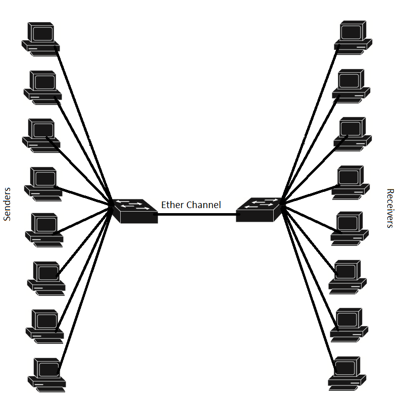
For our project we needed to make sure we could stress test the entire environment to its maximum bandwidth potential. To do this using the above UDP program, we needed to have 8 computers sending the UDP data to 8 computers receiving. Therefore we had a total of 16 computers, 8 on each switch. With a 8 link aggregation, we ensured that all of the senders were on one switch and all of the receivers were on the other switch forcing the traffic to go across the etherchannel link aggregation that we created.

Step 4 – Testing Results
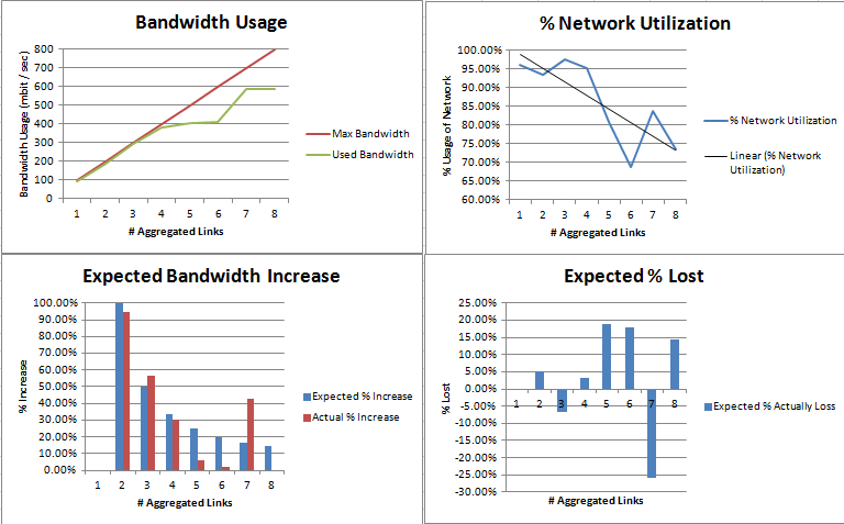
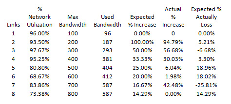
From our testing, we were able to gather the following data for analysis. We were surprised to notice that when adding an additional link from 7 to 8, we had no increase in bandwidth that the switches actually took advantage of. Instead we saw that the switches throttled back specific machines in which we could not find any pattern for.
We found that the most efficient combination of etherlinks in a etherchannel configuration was 3 links which used approximately 97% of the network utilization available to it. There is still reason for providing more links besides bandwidth. The more links that were included in the configuration served as a redundant connection between switches. We demonstrated this by being able to slowly disconnect up to 7 links from our etherchannel and watch the switches automatically recover and send the data was going over the now disconnected link onto a link that was still established.
Our research and our graphs show that the more etherchannel links that you have, the less utilization you will achieve on those links overall. There is a downward trend in utilization as the number of links increase.
Other surprising finds of data was that at 7 links compared to 6 links, we gained 170mbit of additional traffic instead of just 100mbit for the added link. This demonstrates that etherchannel does not always operate on an exact ratio and does not perform as expected always.


Conclusion
As a result of our configuration, testing methodology, and testing results we can confirm that link aggregation is an appropriate communications protocol to use when attempting to create redundant linked backbone switches. While it is true that we could negate the performance loss between the added links by using one high speed gigabit connection, we cannot duplicate the reliability of the communication between these switches by using a sole gigabit connection. We therefore can suggest and even recommend that when mission critical systems are used for internetworking, that link aggregation be setup and configured for at least the reliability aspect.
Created: 11/19/2011 by Monique Moison and Joshua Platz
