Packet Tracer Instructions: Difference between revisions
| Line 149: | Line 149: | ||
*'''PC1''' and '''PC2''' are Configured using the same step of Configuration for the Server above. | *'''PC1''' and '''PC2''' are Configured using the same step of Configuration for the Server above. | ||
[[File:pkt17.PNG|647px]] | [[File:pkt17.PNG|647px]] | ||
| Line 161: | Line 162: | ||
Click on the '''Router1''', make sure that the power of the router is on, and then click on the '''CLI''' tab. If you see a question says "Continue with configuration dialog? [yes/no]:" type no and press Enter key. Press Enter key couple times until you see "Router>". | Click on the '''Router1''', make sure that the power of the router is on, and then click on the '''CLI''' tab. If you see a question says "Continue with configuration dialog? [yes/no]:" type no and press Enter key. Press Enter key couple times until you see "Router>". | ||
When you see "'''Router>'''", copy the command bellow and past the command into the windows by clicking on the '''Paste''' bottom. | When you see "'''Router>'''", copy the ''Italic'' command bellow and past the command into the windows by clicking on the '''Paste''' bottom. | ||
'' | |||
! | |||
enable | |||
configure terminal | |||
ip name-server 192.168.254.254 | |||
interface Serial0/0/0 | |||
ip address 10.10.10.5 255.255.255.252 | |||
no shutdown | |||
exit | |||
interface FastEthernet0/0 | |||
ip address 172.16.255.254 255.255.0.0 | |||
no shutdown | |||
exit | |||
ip route 0.0.0.0 0.0.0.0 10.10.10.6 | |||
end | |||
copy running-config startup-config | |||
exit | |||
! | |||
'' | |||
[[File:pkt19.PNG|647px]] | |||
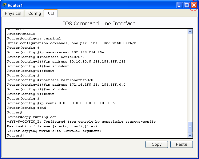
After you paste the command above, you should see this: | |||
[[File:pkt120.PNG|647px]] | |||
Close this windows. | |||
* | |||
Revision as of 23:02, 28 February 2010
Package Tracer Instructions
Cisco Packet Tracer is a powerful network simulation program that allows us to create a network with an almost unlimited number of devices, encouraging practice, discovery, and troubleshooting. The main objective of Packet Tracer is to serve as a support tool for the Cisco Academy. This tool is extremely useful for both students and teachers. In this page, I will walk you through step by step of how to download, install and build a network lab that we use in the CCNA1 using Package Tracer. This instruction is best for a student who have an account to login to the Cisco Networking Academy home page.
Downloading & Installing Package Tracer
Packet Tracer 5.2 is the latest version of Cisco's simulation software available. To download Package Tracer, follow the instruction below:
How to download
- Step 1
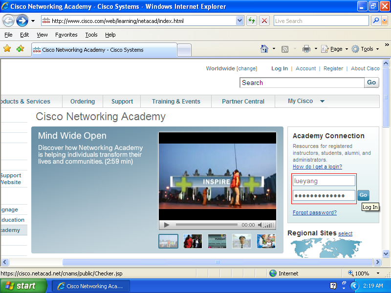
Go to Cisco Networking Academy home page
(NOTE: Make sure to hold Ctrl key to open the link in a new tab.)
- Step 2
Login onto the Student Home using your username and password.
- Step 3
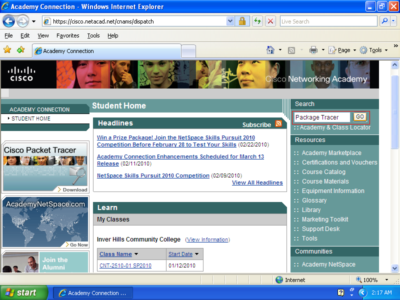
On the Student Home page, type Package Tracer in the search box and press GO or Enter key to search for the software.
- Step 4
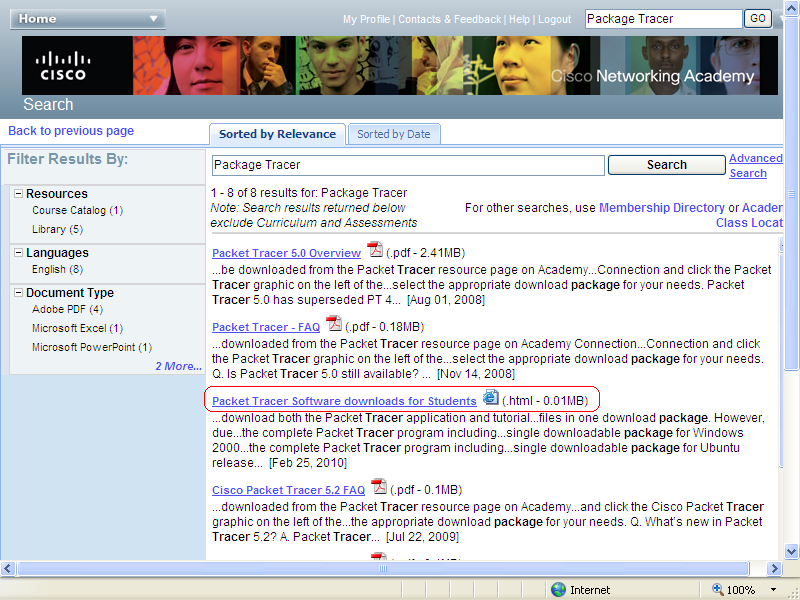
Scroll down to find Packet Tracer Software downloads for Students (.html - 0.01MB). Click on the link and a new windows will prompt.
- Step 5
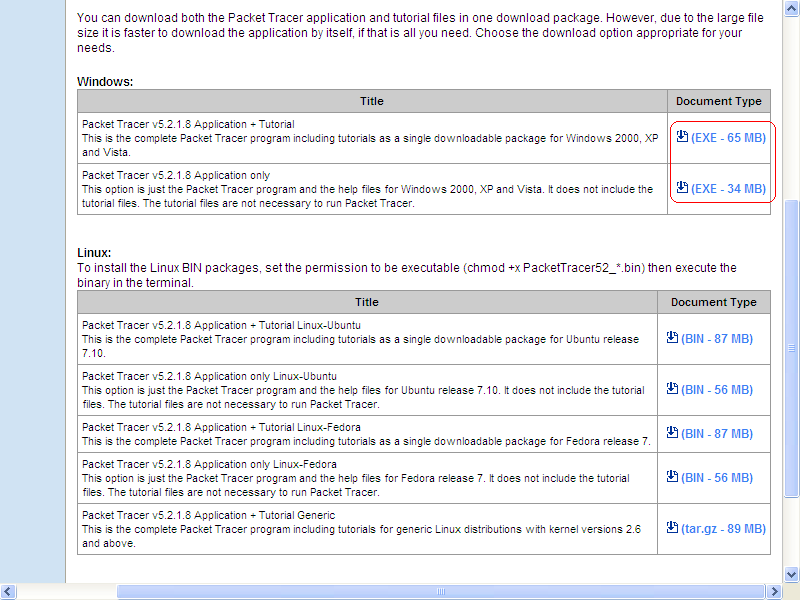
To download, click (EXE - 34 MB), or (EXE - 65 MB) if you want to include tutorials in a single package.
Installation
- Step 1
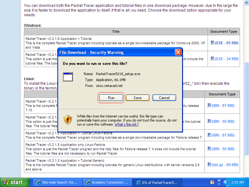
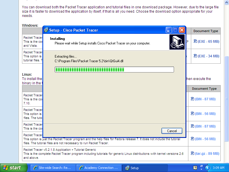
And, then click Run to run the installation process after downloaded.
The screen shots below will show you through each step of the installation process.
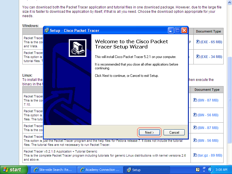
- Step 2
Click next
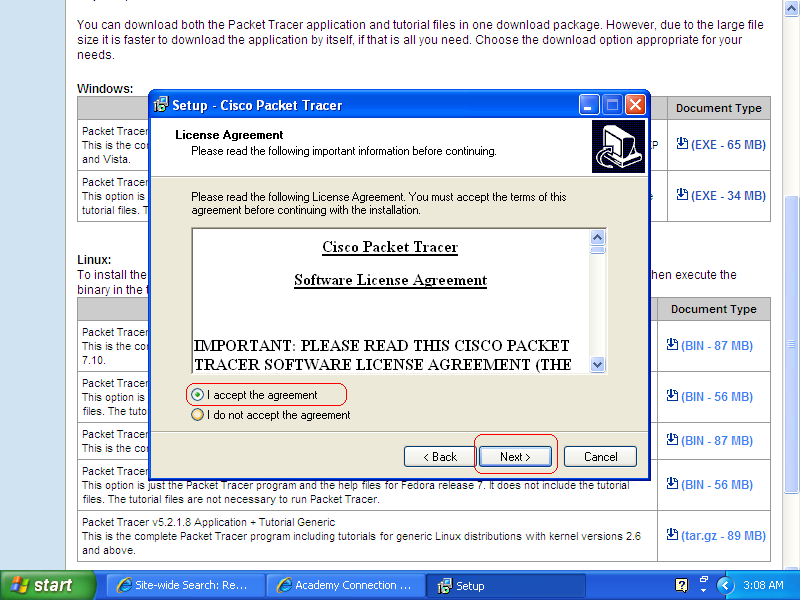
- Step 3
In oder to install the software, you must check I accept the agreement and click the Next button.
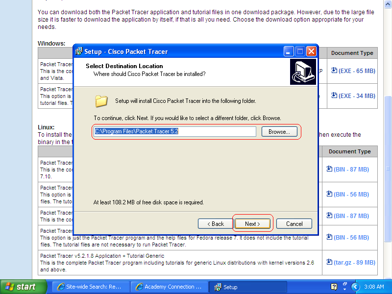
- Step 4
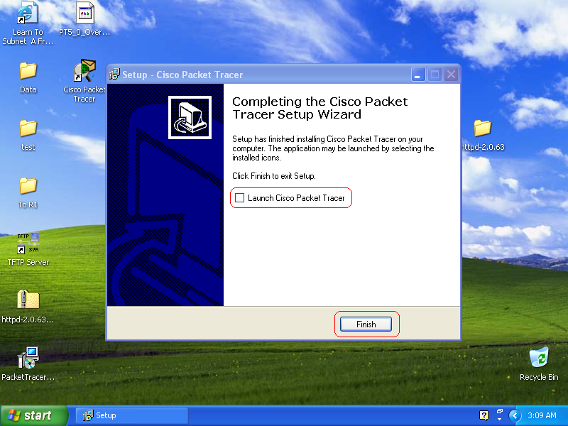
- Step 5
Click the Finish button.
Now you are completed with installation. The next step will show you how to use Cisco Package Tracer.
Using Cisco Package Tracer
The next step, I will show you how to use Package Tracer by building a basic network.
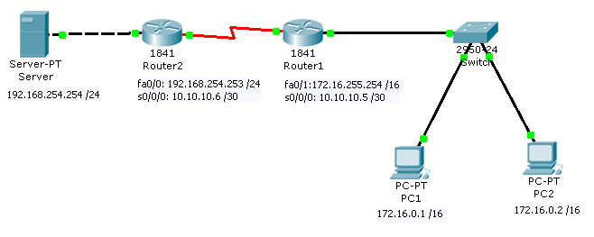
Below is the topology of the network. I will use the IP Address in this topology to configure the network connection.
Building Cisco equipment and hardware
Follow the bellow steps to create the network topology above.
- Step 1
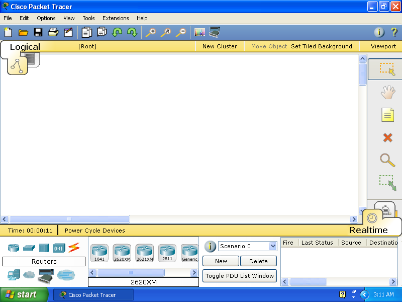
Double click the Cisco Package Tracer icon on the desktop, the Cisco Package Tracer windows will open as shown below:
- Step 2
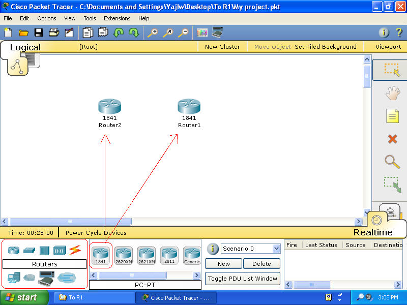
To create the Routers icon locates on the bellow left-hand conner, then click on the models that appear next to the right. Click and draft the model you want to the work area. Click the name of the routers to change them if you want.
- Step 3
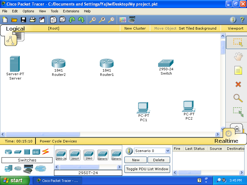
Click the the Switches icon, and then click and draft the model you want to the work area.
-Follow the step to create PC1, PC2, and the Server.
- Step 5
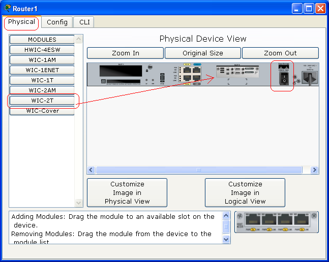
Click on Router1, under Physical tab, you will see the physical device picture under Physical Device View. turn it off, and then click and draft the modules WIC-2T to one of the expansion slots of the router, and then turn it on.
-Follow the same step for Router2.
Connecting and Cabling
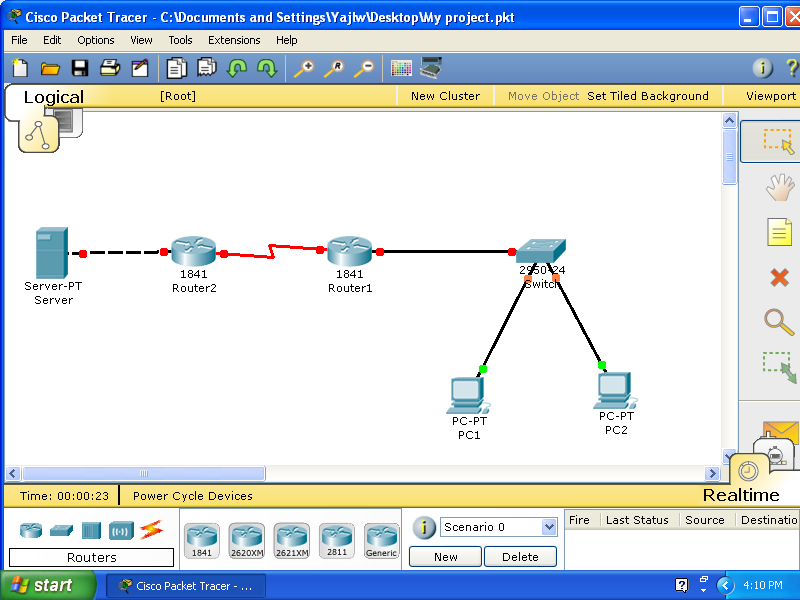
To connect all the devices together, click the Connection icon, and then click the right cable.
- (Note)Make sure to use the right cables.
From PC1, PC2 and Router1 to the Switch, we use Copper Straight-Through cable. Between Router1and Router2, we use Serial DCE cable. And, between Server and Router2 we use Copper Cross-Over cable.
configuring Devices
To make communication between the device, each device needed to be configured correctly.
- Configuration for the Server:
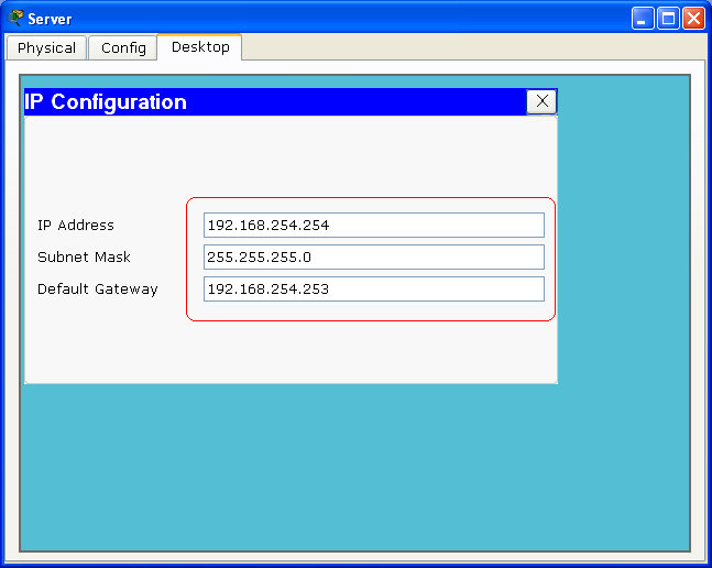
First, click on the Server and make sure the power is on. Under Desktop tab, click on the IP Configuration icon, and input the IP Address, Subnet Mask, and Default Gateway as shown bellow. Click the red X of the Sever Windows to close the configuration.
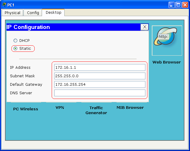
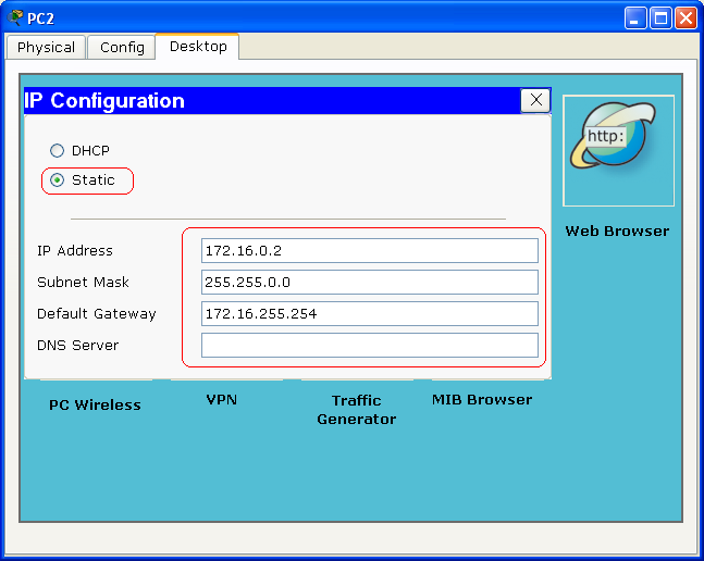
- PC1 and PC2 are Configured using the same step of Configuration for the Server above.
- Configuring Router1:
Now you have all the end devices configured. The next step is to configure the two routers.
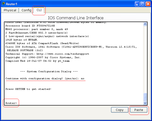
Click on the Router1, make sure that the power of the router is on, and then click on the CLI tab. If you see a question says "Continue with configuration dialog? [yes/no]:" type no and press Enter key. Press Enter key couple times until you see "Router>".
When you see "Router>", copy the Italic command bellow and past the command into the windows by clicking on the Paste bottom.
! enable configure terminal ip name-server 192.168.254.254
interface Serial0/0/0
ip address 10.10.10.5 255.255.255.252
no shutdown
exit
interface FastEthernet0/0
ip address 172.16.255.254 255.255.0.0
no shutdown
exit
ip route 0.0.0.0 0.0.0.0 10.10.10.6 end
copy running-config startup-config
exit !
After you paste the command above, you should see this:
Close this windows.
